DataHand Keyboard Finger Board Circuit

Abstract

This page will help you repair DataHand keyboards - if that's too much for you, then contact me and I might buy they keyboard off you or else charge to repair it.

Info

The DataHand keyboard is the best keyboard in the world, period.

I've had two datahands for a couple decades, and sometimes they need some maintenance. Sometimes, a good DataHand cleaning solves the problem, but I've also had keys stop working.

When this happens:

  1. Try a thorough DataHand cleaning. Their are no components on the board that has the finger keys except the LEDs and the optical switches, so they can even handle water directly. I know of one person who puts his in the dishwasher, though I haven't been brave enough to try that.
  2. Try resoldering the pins on the back of the board. Put a soldering iron on lowheat and then just touch to the pins until it remelts, it can take just a couple seconds. This can help if the connection to one pin has cracked.
  3. If part of a trace is actually broken, it's not too hard to find the problem with a simple multimeter checking for continuity (and maybe if you use the diode tester.) That's what the rest of this page is about.

Repair

Here's the circuit board for the right finger unit to show you how everything is connected and how it works. Click on it for a larger image:

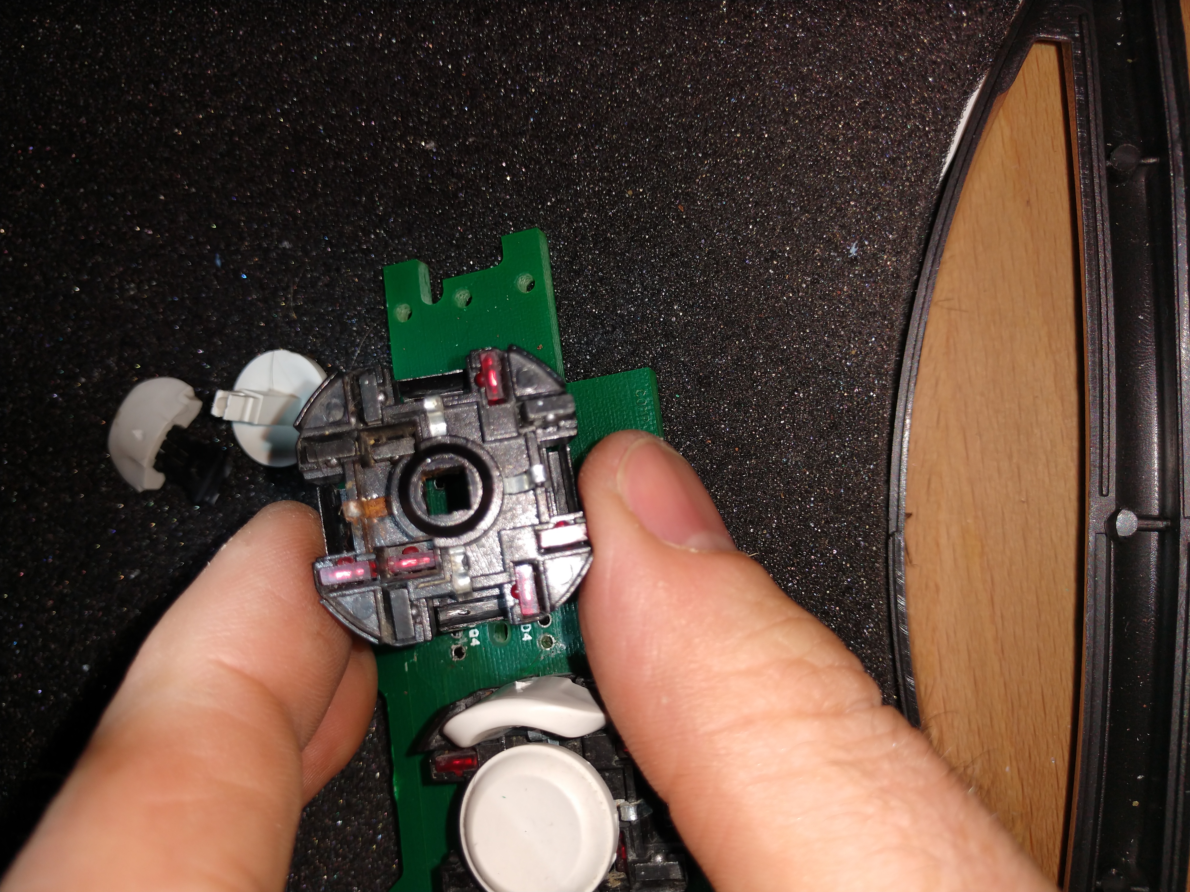
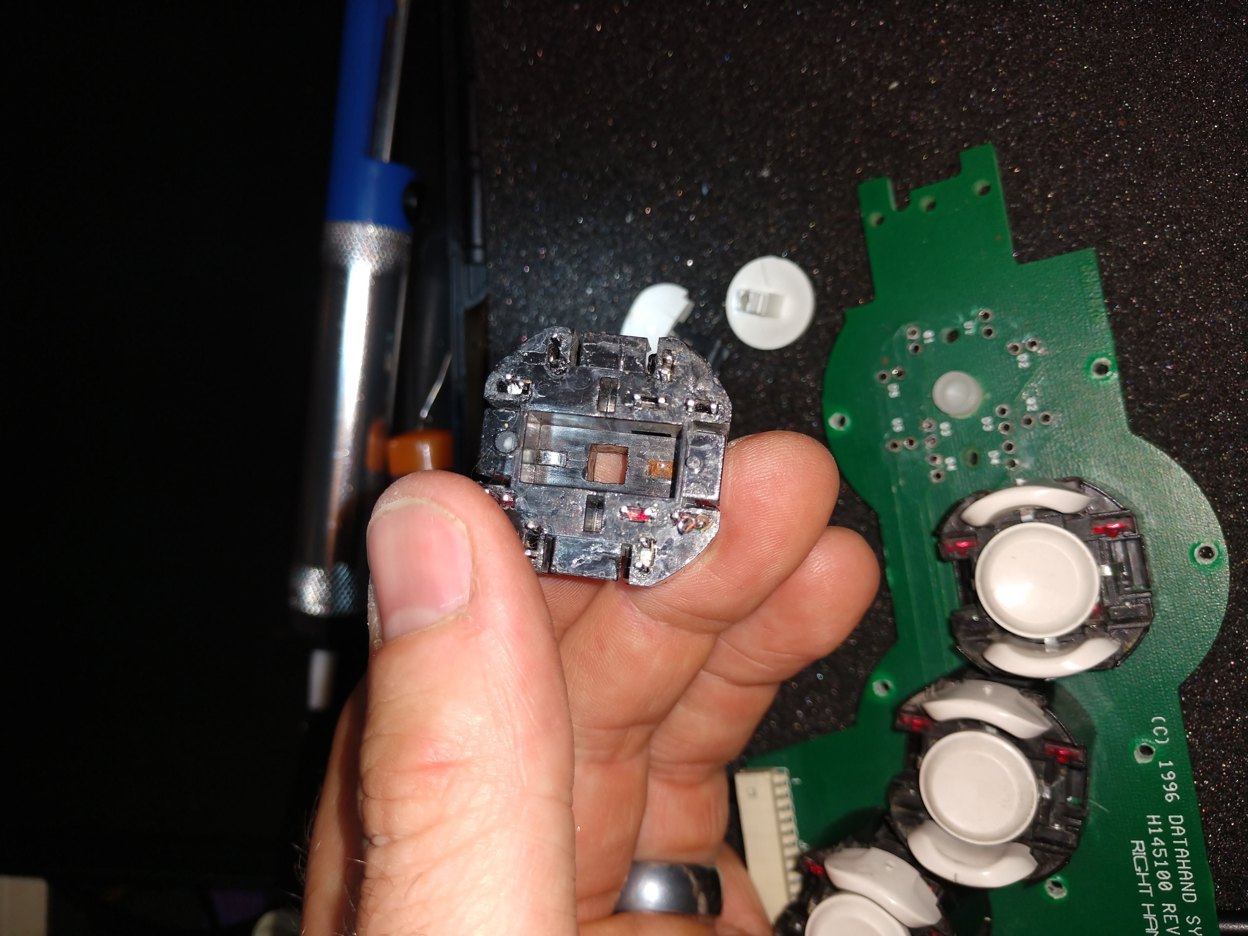
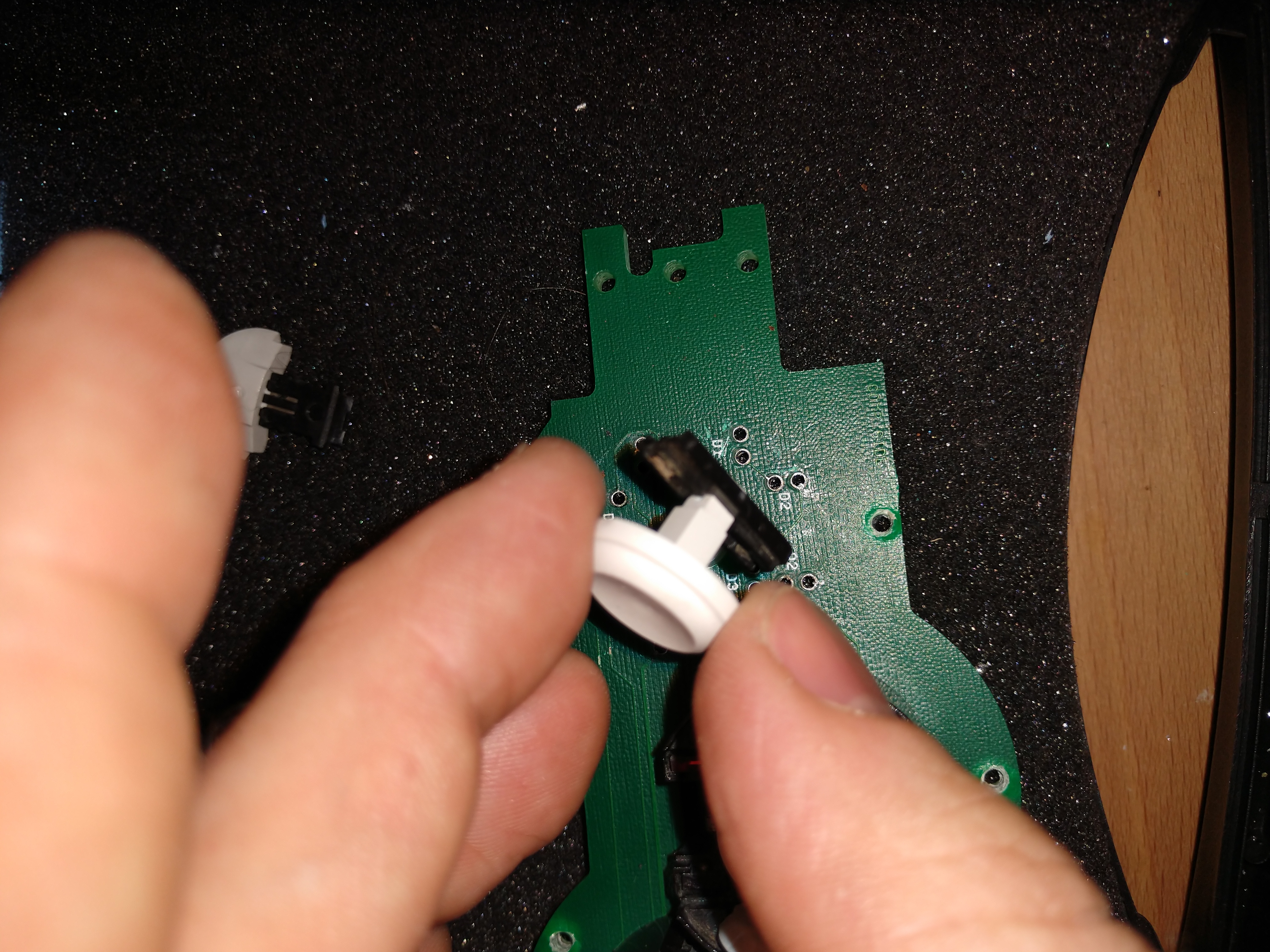
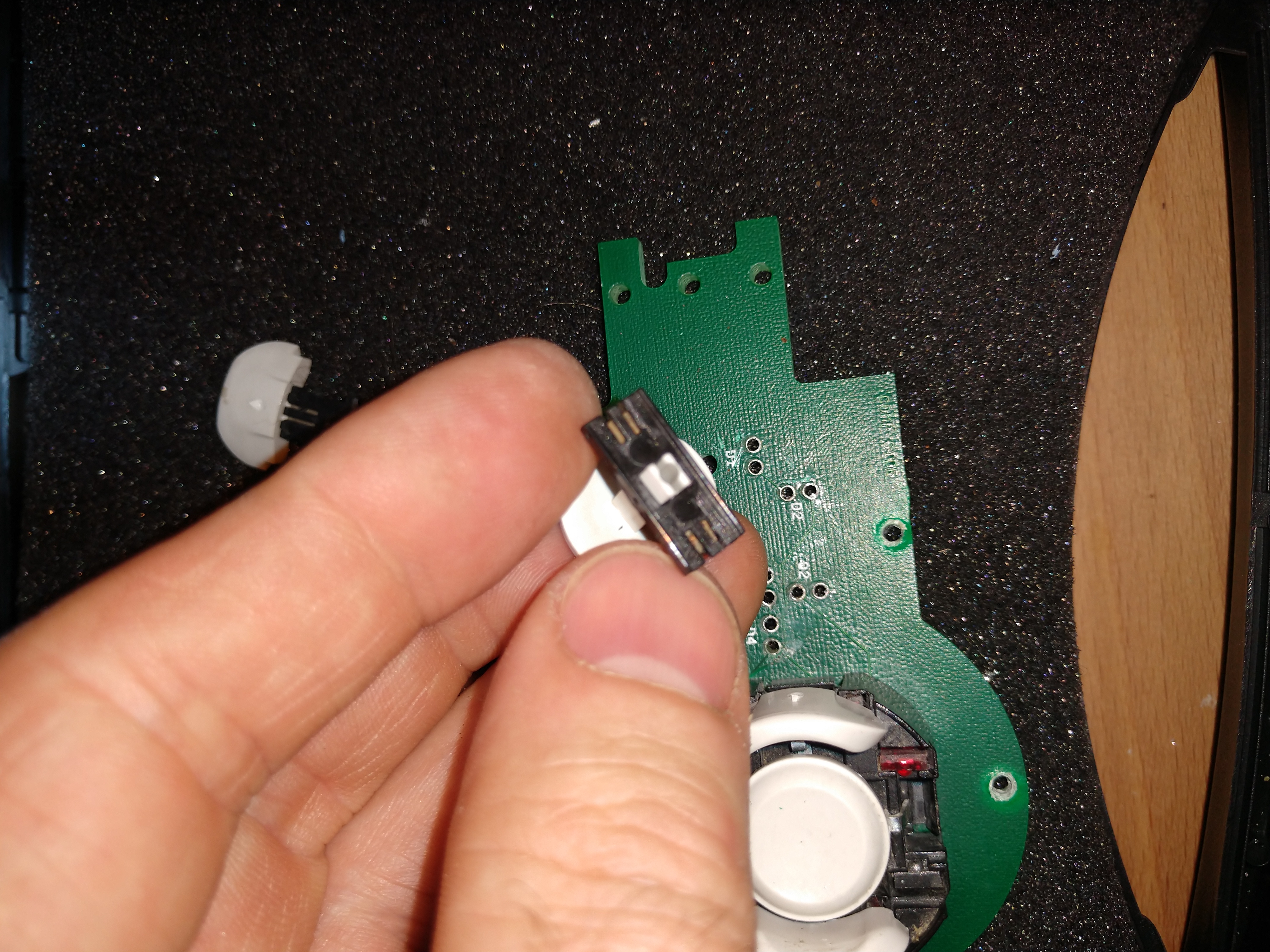
Figure 1.1a - The DataHand Finger Circuit Board
Click for full resolution
There's a 14 pin connector on the bottom, I've labelled the pins A-N, with different colors:

Pin(s) Color What
L Red Diode positive (for two diodes in series)
E Black Switch ground
M Blue Switch set 1 positive
N Cyan Switch set 2 positive
A-K (except E) yellow Diode ground switch

There are a number of pins that are supposed to be connected to each other and/or to the 14 pin connector. Use the continuity tester to see what's broken and simply solder a wire across the two points to reconnect them - obviously focusing on the keys that are broken.

Each finger board has 20 optical switches (5 for each finger) composed of an LED/emitter and a switch/receptor. (See bottom of page for photos)

Effectively all of the switches are connected to E on one side (which I've called "switch ground" though I don't actually know the polarity, and then half the other side of the switches are connected to "Switch set 1 positive" and "Switch set 2 positive". Though again I don't know the polarity or the actual exact specific components used for the switch.

Then the LEDs are paired up and powered in series, all of the positive being hooked up at L, but each of the negatives hooked up to the 10 yellow pins. Then the DataHand can cycle through connecting each of the yellow pins to ground, causing the diodes to turn on two at a time.

For each pair of LEDs, there are the pair of switches, both of them have one side connected to E, and the other side either connected to M or N.

The operation is something like this: Positive voltage is always applied to "L"

  1. Connect A to ground - this turns on the two LEDs on the far left of the board (upside down) - these are the LEDs for the right pinky pressing down or pressing right (the ';' and '\' keys)
  2. Check E->M switch. This tells you if '\' is pressed
  3. Check E->N switch. This tells you if ';' is pressed
  4. Disconnect A. Connect B to ground (turns on LEDs for 'p' and 'n')
  5. Check E->M switch. This tells you if 'p' is pressed
  6. Check E->N switch. This tells you if 'n' is pressed
  7. etc...


This is what the switch units look like when you take them off the board:


Back to my DataHand page